So far, we have set up several Kubernetes master and worker nodes, configuring networking between them to ensure they can all communicate. We also ensured that the firewall and network security groups are correctly configured, allowing the Kubernetes control plane components to communicate.
Setting the Stage
Assume that we have set up all the Kubernetes control plane components such as the kube API server, etcd servers, kubelets, etc. We are now ready to deploy our applications. However, before proceeding, we must address the networking at the pod layer. Our Kubernetes cluster will soon have a large number of pods and services running on it.
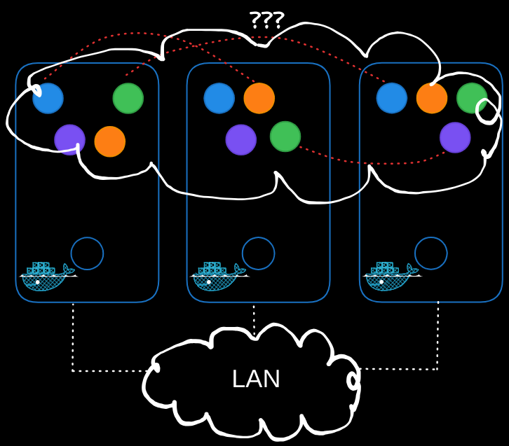
Challenges in Pod Networking
- Pod Addressing and Communication: How are the pods addressed? How do they communicate with each other?
- Service Accessibility: How do you access services running on these pods internally within the cluster and externally from outside the cluster?
Kubernetes does not come with a built-in solution for these challenges but expects you to implement a networking solution. However, Kubernetes clearly outlines the requirements for pod networking:
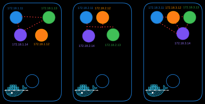
- Every pod must have its own unique IP address.
- Every pod should be able to reach every other pod within the same node using that IP address.
- Every pod should be able to reach every other pod on other nodes without NAT.
Implementing Pod Networking
Let’s take a look at how we can enable pod networking.
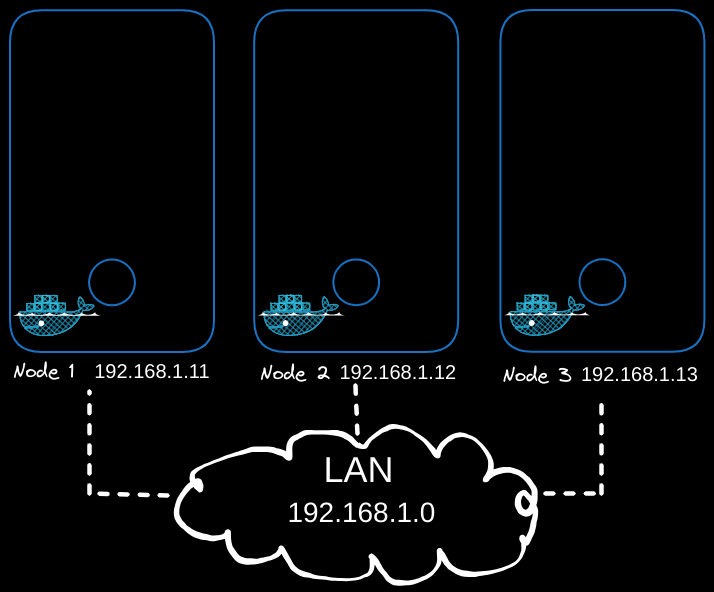
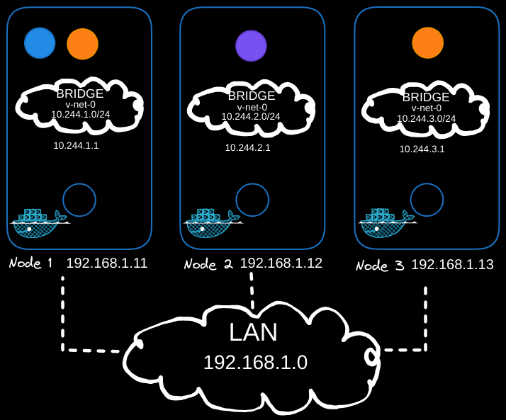
In the above example, we have a three-node cluster, and it doesn’t matter which one is master or worker as they all run pods. These nodes are part of an external network with IP addresses in the 192.168.1 series:
- Node one is assigned 192.168.1.11,
- Node two is 192.168.1.12,
- Node three is 192.168.1.13.
Bridge Networks
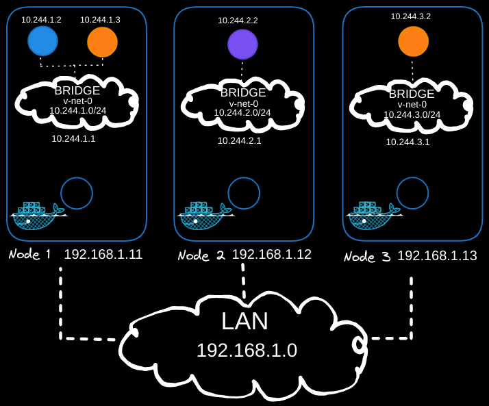
When containers are created, Kubernetes creates network namespaces for them. To enable communication between them, we attach these namespaces to a network using bridge networks on each node. Each bridge network is assigned its own subnet:
- 10.240.1 for node one,
- 10.240.2 for node two,
- 10.240.3 for node three.
This is done like so for each node, which will use a different IP address:
# Create a bridge network
ip link add v-net-0 type bridge

# Bring the bridge interface up
ip link set dev v-net-0 up

# Assign an IP address to the bridge
ip addr add 10.240.1.1/24 dev v-net-0  # Adjust for each node's subnet
Connecting Containers
For each container, a script is written to:
- Create a virtual network cable using the
ip link addcommand. - Attach one end to the container and the other end to the bridge using the
ip link setcommand. - Assign an IP address using the
ip addrcommand. - Add a route to the default gateway.
# Create a veth pair
ip link add veth0 type veth peer name veth1

# Attach veth pair
ip link set veth0 master v-net-0
ip link set veth0 up
ip link set veth1 netns <namespace>

# Assign IP Address
ip -n <namespace> addr add 10.240.1.2/24 dev veth1  # Use a unique IP
ip -n <namespace> route add default via 10.240.1.1

# Bring Up Interface
ip -n <namespace> link set veth1 up
This script is run for each container to connect them to the network, enabling communication between containers on the same node.
Cross-Node Communication
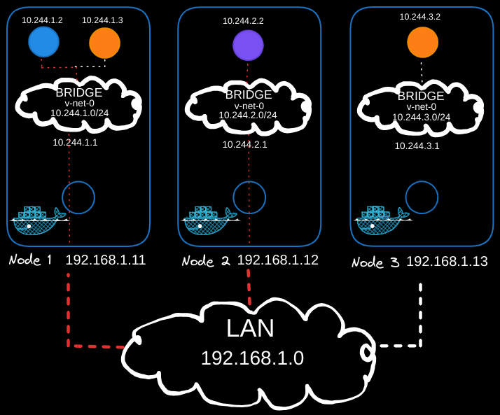
To enable pods on one node to communicate with pods on another, routing must be configured between the nodes. For example, the blue pod (10.244.1.2) on Node 1 should be able to reach the purple pod (10.244.2.2) on Node 2.
As of now, the blue pod (10.244.1.2) has no direct knowledge of the purple pod’s address (10.244.2.2) because it resides in a different subnet. When the blue pod sends traffic to 10.244.2.2, it forwards the traffic to its default gateway, which is the bridge interface of Node 1 (10.244.1.1).
Node 1’s bridge interface then attempts to route the traffic. However, Node 1 does not inherently know how to reach the 10.244.2.0/24 subnet on Node 2 because it is part of a private network. Without additional routing configuration, Node 1 will drop the packet, preventing the blue pod from reaching its destination.
Solution: Add Static Routes
To enable Node 1 to forward traffic to Node 2’s subnet and vice versa, static routes must be added to each node’s routing table.
On Node 1
Add a route to direct traffic for the 10.244.2.0/24 subnet (Node 2’s pod network) via Node 2’s external IP (192.168.1.12):
ip route add 10.244.2.0/24 via 192.168.1.12
When Node 1 receives traffic from the blue pod (10.244.1.2) destined for the purple pod (10.244.2.2), it forwards the packet to Node 2’s external IP (192.168.1.12) using its external network interface (eth0).
On Node 2
Add a route to direct traffic for the 10.244.1.0/24 subnet (Node 1’s pod network) via Node 1’s external IP (192.168.1.11):
ip route add 10.244.1.0/24 via 192.168.1.11
When Node 2 receives the packet, it checks its routing table and recognizes that 10.244.2.2 belongs to its local subnet (10.244.2.0/24). It then delivers the packet to the purple pod via its bridge interface (10.244.2.1).
Repeat for Additional Nodes
Repeat this process for all nodes in the cluster to ensure that each node has routes to the other nodes' pod subnets.
This configuration ensures seamless communication between pods across different nodes by:
- Leveraging the default gateway for initial traffic forwarding from the pod.
- Using static routes for inter-node communication.
Verification
To verify inter-node connectivity, test by pinging from one pod to another across nodes:
# From the node with the blue pod
ping 10.244.2.2
If the routes are configured correctly, the blue pod (10.244.1.2) will successfully communicate with the purple pod (10.244.2.2).
Optimizing Routing with a Central Router
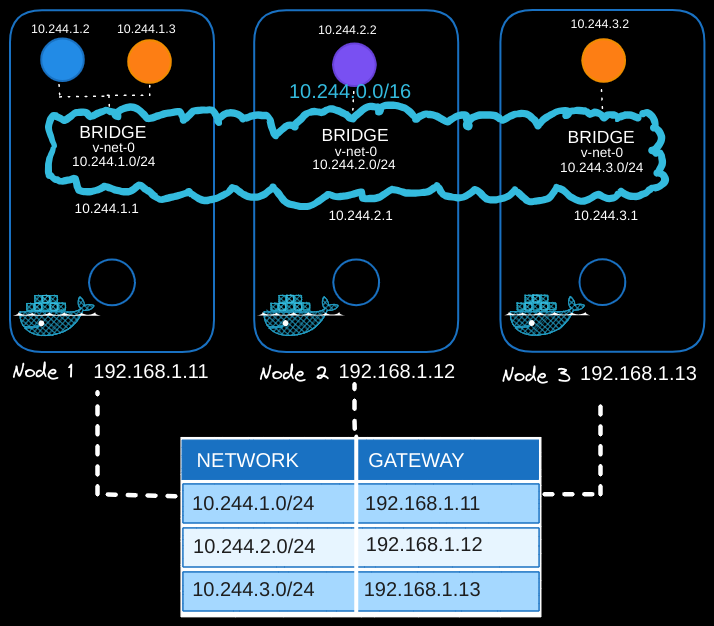
Manually adding routes to each node can become complex in larger clusters. A central router simplifies this process:
-
Centralized Route Management:
- Configure a router with the routing table for all pod subnets (
10.244.0.0/16). - Set the router as the default gateway for all nodes.
- Configure a router with the routing table for all pod subnets (
-
Benefits:
- Reduces the need to manually configure routes on each node.
- Centralizes routing management, making it easier to handle network changes.
Unified Pod Network
Once routing is configured, the individual subnets (10.244.1.0/24, 10.244.2.0/24, etc.) form a single large network (10.244.0.0/16), enabling seamless communication between pods across the cluster.
Automating Networking with CNI
Manually setting up networking and routing is not scalable. To automate this process, Kubernetes relies on CNI (Container Network Interface) plugins.
What is CNI?
- CNI acts as a middleman between Kubernetes and custom networking scripts or tools.
- It defines how Kubernetes interacts with networking when pods are created or destroyed.
How CNI Works
- Container Runtime Calls CNI: When a container (pod) is created, the container runtime (e.g., containerd, Docker) looks at the CNI configuration passed during setup.
- CNI Executes Scripts: The runtime executes the CNI script, which takes care of:
- Adding the container to the network (
addcommand). - Cleaning up when the container is deleted (
deletecommand).
- Adding the container to the network (
Modifying the Script for CNI
The script we wrote earlier must be updated to meet CNI standards:
- Add Section: Adds a container to the network.
- Delete Section: Removes a container and cleans up resources.
Here’s a CNI-compliant script:
#!/bin/bash

COMMAND=$1  # "add" or "delete"
NAMESPACE=$2
POD_IP=$3
BRIDGE="v-net-0"
GATEWAY="10.244.1.1"

case "$COMMAND" in
  "add")
    # Create veth pair
    ip link add veth0 type veth peer name veth1

    # Attach veth0 to the bridge
    ip link set veth0 master $BRIDGE
    ip link set veth0 up

    # Move veth1 to container namespace
    ip link set veth1 netns $NAMESPACE

    # Configure veth1 inside container namespace
    ip -n $NAMESPACE addr add $POD_IP/24 dev veth1
    ip -n $NAMESPACE route add default via $GATEWAY
    ip -n $NAMESPACE link set veth1 up
    ;;
  "delete")
    # Find and delete veth pair by name
    ip link delete veth0
    ;;
esac
How CNI Invokes the Script
- The script is placed in the CNI bin directory (e.g.,
/opt/cni/bin). - A CNI configuration file is created (e.g.,
/etc/cni/net.d/10-custom-cni.conf):{ "cniVersion": "0.3.1", "name": "custom-cni", "type": "bridge", "bridge": "v-net-0", "ipam": { "type": "host-local", "subnet": "10.244.0.0/16" } } - Kubernetes calls the CNI plugin whenever a pod is created or deleted. The plugin executes the corresponding script section.
